Framing Guides Library
Every framing reference you need: annotated wall diagrams, on-center layout deep dives, 2026 cost benchmark guides, metal vs wood comparisons, corner framing SOPs, 11-step wall construction sequence, nail & tool kit, IRC code notes, and skill roadmaps from beginner to production.
Framing Calculation: The Math, Methods, and Standards Behind Every Stud
Every framed structure — from a single interior partition to a full 3,000 ft² house shell — depends on three correct inputs: the right count of studs and plates, the right on-center layout so sheathing lands on stud centers, and the right cost budget so the bid does not go underwater after lumber spikes or regional labor premiums hit. Get the stud count wrong and the material takeoff comes up short before the wall is finished. Get the layout wrong and openings, corners, and T-intersections land off-station, failing inspection. Get the cost wrong and a bid that looked profitable turns into a loss. These guides exist to make all three calculations precise, transparent, and reproducible.
Unlike the homepage calculator — which is a single interactive math engine — these guides go deep into one dimension each. The Wall Framing Diagram guide annotates six wall types with SVG callouts and compares 16″ O.C., OVE, and 19.2″ layout methods with a blueprint-to-site layout SOP. The Framing Cost guide builds a total-project cost matrix (material + labor + overhead) benchmarked to 2026 national rates. The Metal Stud guide prices steel framing by gauge, a material system the generic calculator does not cover at all. The 2×4 guide turns the generic calculator into a dedicated procurement reference for the most common stud size, including bundle economics, precut heights, and room-based quick counts.
Each guide was written to be self-contained: open any one of them and you get the full methodology, reference tables, worked examples, and an embedded calculator or sizing terminal where it fits — without being forced to bounce between pages. They are organized into three categories below. Pick the category that matches your question, or read across all four to see how stud count, layout, and cost connect into a single professional workflow.
Featured Framing Guides
Each guide goes deep into one dimension of framing — total cost, steel-stud pricing, annotated layout diagrams, or dedicated 2×4 takeoffs. Browse by category below; every card links to a self-contained guide with reference tables, SVG diagrams, and embedded calculators. The Cost & Pricing and Stud & Material categories pull companion calculator pages alongside the diagram guide so you get the methodology and the math engine in a single flow.
Cost & Pricing Guides
💰Whole-project and steel-stud framing budgets benchmarked to 2026 national rates. Material plus labor plus overhead, broken out per square foot and per linear foot. These guides answer “how much does framing cost” at the whole-house, basement, and commercial TI level, with regional and gauge adjustments.
Framing Cost Calculator Guide
Total project framing cost estimation: per-sq-ft cost matrix by house size, regional labor rates, material vs labor split, basement and interior wall framing costs, and DIY vs contractor comparison benchmarked to 2026 US rates.
Metal Stud Framing Cost Guide
Steel and metal stud framing cost analysis: gauge-based pricing per linear foot (20/22/25/27 ga), steel vs wood cost comparison matrix, commercial vs basement TI application scenarios, and on-center spacing impact on total installed cost.
Layout & Diagram Guides
📐Annotated wall framing reference and on-center layout methodology. Pure SVG callouts, layout method comparison, and a blueprint-to-site SOP. Covers interior, exterior, corner, T-intersection, and gable-end wall types with component-level annotations.
Stud & Material Calculation Guides
🪵Dedicated takeoff guides for specific lumber sizes, with actual-size conversion, bundle economics, span tables, room-based quick counts, and procurement-oriented cut lists.
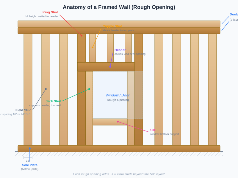
🧱 Anatomy of a Framed Wall: Component Library
Before you can count studs or lay out a plate, you need to know what each component is called and what it does. Most rookie takeoff errors come from confusing a king stud with a jack stud, or forgetting that every window needs a rough sill plus sill cripples below it. The Wall Framing Diagram guide dedicates a full SVG library to each component type; below is the at-a-glance reference so you can follow along with any guide on this site.
The bulk of any framed wall — field studs carry vertical loads and provide nailing for sheathing and drywall.
Frames the outside of every rough opening; the jack (trimmer) stud nails against it to support the header ends.
Load-bearing member under each header end. Most openings need two jack studs minimum; wide spans get doubled or tripled trimmers.
Header cripples keep the top-plate layout continuous; sill cripples support the window rough sill from below.
Full 8-component deep dive with cross-section callouts in the Diagram guide's SVG library.
All Eight Framing Wall Components Defined
Every calculator and guide on this site models the wall using these eight components. When you run a takeoff and the result says “+ 4 opening studs”, those 4 are king + jack pairs. When it says “+ 3 corner studs”, those are the traditional three-stud corner build-up. Memorizing these eight names and roles lets you sanity-check any calculator output against the physical wall you are building.
Field (Common) Stud
Full-height vertical member spaced at regular on-center intervals (16″, 19.2″, or 24″ O.C.) between the sole plate and the top plate.
The bulk of any framed wall — field studs carry vertical loads and provide nailing for sheathing and drywall.
King Stud
Full-height stud running floor to ceiling on each side of a door or window opening. Continuous and not interrupted by the header.
Frames the outside of every rough opening; the jack (trimmer) stud nails against it to support the header ends.
Jack Stud (Trimmer)
Shorter stud sitting on the bottom plate and supporting the end of the header on each side of an opening. Height = header bottom to sole plate.
Load-bearing member under each header end. Most openings need two jack studs minimum; wide spans get doubled or tripled trimmers.
Cripple Stud
Short stud that fills the gap above a header down to the top plate, or below a window rough sill down to the sole plate.
Header cripples keep the top-plate layout continuous; sill cripples support the window rough sill from below.
Header
Beam spanning the top of a door or window opening, transferring loads above the opening down to the jack studs on each side.
Sizes set by span and load per IRC Table R602.7. Typical 3-ft openings use a double 2×12 or built-up LVL header.
Rough Sill
Horizontal member at the bottom of a window opening, running between the jack studs and supported by sill cripples.
Provides a flat nailing base for the window unit; not needed for doors.
Bottom (Sole) Plate
Single horizontal 2× member anchored to the floor slab or subfloor; studs toenail or face-nail into it.
Use pressure-treated (PT) lumber where the plate sits on concrete or masonry to resist wicking moisture per IRC R602.1.2.
Double Top Plate
Two stacked horizontal 2× members capping the studs. Second layer laps joints by ≥ 4 ft and ties intersecting walls together.
Standard on all exterior and load-bearing walls. Non-bearing partitions may use single top plate if code allows (advanced framing / OVE).
On-Center Layout Methods: 16″ vs 19.2″ vs 24″ O.C.
Spacing is the single biggest decision you make on any framing takeoff. Pick the wrong layout and you either waste lumber (16″ O.C. on a non-bearing partition) or risk a drywall crew cursing your name because field joints do not land on studs (24″ O.C. without a proper edge-nailing schedule). The Wall Framing Diagram guide compares all four modes with SVG layout overlays; below is the side-by-side cheat sheet for the three you will use 99% of the time.
16″ O.C. — The Default
Load-bearing exterior / StandardPanel Alignment
Every 4-ft sheet edge and every sheet break lands perfectly on a stud center.
When to Use It
Any exterior load-bearing wall, IRC Table R602.3.1 general case, walls receiving tile or stone finishes.
✓ Pros
Maximum drywall backing, code-accepted everywhere, matches sheathing geometry perfectly.
✗ Cons
Highest stud count of the three mainstream modes — about 33% more lumber than 24″ O.C.
19.2″ O.C. — The Production Sweet Spot
Single-story / Upper floors / Tract homesPanel Alignment
Studs land exactly at 4′, 8′, 12′, 16′ breaks — the 5th stud every 8 ft is the key.
When to Use It
Production tract builders on single-story or upper-floor walls where 24″ feels too flexible but 16″ feels wasteful.
✓ Pros
Saves 20% lumber vs 16″ O.C. while still putting a stud at every 4-ft sheet joint. IRC-accepted when paired with correct stud size.
✗ Cons
Many crews are unfamiliar with the spacing; layout marks must be precise because the pattern does not self-check as obviously as 16″.
24″ O.C. — Advanced Framing (OVE)
Non-bearing partitions / 2×6 exteriorsPanel Alignment
Sheet edges on stud, but mid-panel field joints do NOT hit a stud — requires edge nailing schedules.
When to Use It
Interior non-bearing partitions, exterior 2×6 walls with advanced framing, single-story homes in mild wind zones.
✓ Pros
Roughly 33% fewer studs than 16″ O.C., 50% more insulation cavity per wall. 2×6 @ 24″ can outperform 2×4 @ 16″ on R-value.
✗ Cons
Requires drywall crew to hit edge nailing schedule on field joints. Taller walls must go 2×6 to avoid buckling under wind/axial loads.
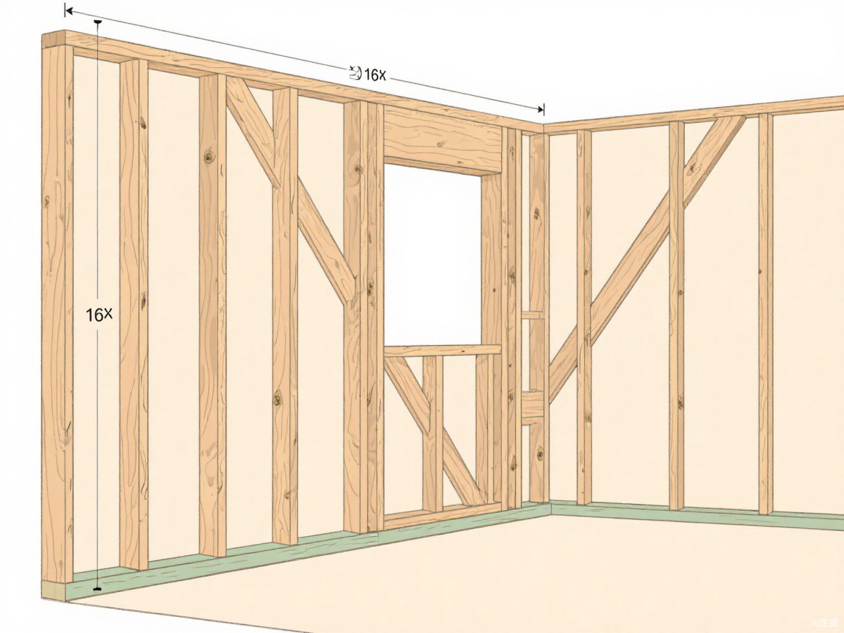
🏗️ How to Build a Wall Frame: 11-Step SOP
The Wall Framing Diagram guide distills the industry-standard build sequence into 11 ordered steps, each with a gotcha and a common rookie mistake. Follow this exact sequence and every wall you stand will be plumb, square, and inspection-ready the first time. Skip a step — say, forgetting to stagger the double-top-plate joints — and you create a hidden weak point that does not show up until the roof load goes on.
Below is each step at a glance; open the Diagram guide for the per-step checklist, nail counts, and photos of crews doing it right (and wrong). If you are self-performing and learning on the job, read steps 6 through 9 twice — standing a wall is when mistakes become expensive to fix.
Measure & Snap the Plate Line
📏Confirm the wall length and stud height off the plans. Chalk a straight sole-plate line on the floor slab or subfloor. Double-check corners are square with a 3-4-5 triangle or a laser — a 1/8″ out-of-square corner at the plate grows to 1/2″ by the time you stand the wall and sheath it.
Gather Material & Kit the Plates
🪚Cut one bottom plate and two top plates to the exact wall length. For walls longer than your stock board, lap top-plate joints by a minimum of 4 ft and offset the two layers so no two joints land on the same bay. This staggered lap is what gives the double top plate its continuity strength.
Lay Out O.C. Marks on the Plates
📐Hook your tape on the end of the bottom plate. Strike lines every 16″, 19.2″, or 24″ all the way down. Transfer the same marks to both top plates by stacking them. Mark each line with two V-shaped arrows so you know which side the stud center lands on — this prevents a 16″ layout from accidentally becoming a 14.5″ layout.
Mark Rough Openings on the Layout
🚪Use the RO (rough opening) sizes from the window/door schedule. Mark king studs full-height, then mark the trimmers inside, the header length between trimmer tops, and (for windows) the rough sill and sill cripples below. A common rookie mistake is marking header length as door width — it is door width + trimmer thickness on both sides + 1/8″ shim gap.
Cut Studs, Kings, Jacks, Cripples, Headers
✂️Cut field studs to the common height — precuts for 8-ft (92⅝″), 9-ft (104⅝″), and 10-ft (116⅝″) walls save hours of chop-saw time. Cut jacks shorter by exactly the header depth. Build headers as doubled-up 2× stock with a ½″ plywood skin or specified engineered LVL. Do not cut king studs shorter to fit the header — they run full height.
Assemble the Wall Flat on the Deck
🔨Lay bottom plate and one top plate on edge, parallel. Drop studs, kings, jacks, cripples, and headers between them at the marked lines. Drive two 16d (3½″) nails through the plate into the end of each stud — that is a face-nail connection. If you have a framing nailer, this step takes 30 seconds per stud. If hand-nailing, nail every other stud first to pull the plates straight, then back-fill.
Square, Brace, and Stand the Wall
📐Measure both diagonals of the framed wall; shim or tap until they read equal (within 1/8″). Nail a temporary diagonal brace across the face, then lift the wall with a crew and set the sole plate onto the chalk line. Never walk away from a standing wall that is only tacked — one gust of wind can tip it over before it is plumbed and braced.
Anchor the Sole Plate to the Floor
⚓On concrete, use powder-actuated pins or ¼″ wedge anchors every 4 ft and within 12″ of ends. On wood subfloor, toenail or face-nail with 16d common nails into the joists wherever they align. If the plate sits on concrete, this is the point where you should have used PT lumber per IRC — inspectors will check for a PT stamp or CA-C treated stamp.
Plumb, Brace, Nail Second Top Plate
🧭Shoot a level laser or use a 6-ft level to bring the wall dead plumb; set temporary 2×4 braces every 8–10 ft, nailing into stakes or floor blocking. Then face-nail the doubled top plate on, lapping joints ≥ 4 ft and tying corners and wall intersections. The doubled top plate is what transfers roof and floor loads from above down to the studs, so do not skip it on bearing walls.
Blocking, Fire Stops, Let-In Bracing
🧱Add mid-height solid blocking or approved fire-stop material per IRC R302.11 where bays run taller than 8 ft. Nominal 2× blocking, mineral wool batt, or ½″ plywood strips are common means. Nail let-in 1×4 or metal L-straps on exterior corners and long wall runs for required lateral bracing against wind and seismic loads.
Corners, Intersections, Hand-Off to Next Trade
🤝Build up corner posts or add the intersection ladder blocking. Walk the wall with a gun, spot-check 16d nail counts per plate connection, and mark any header or jack adjustments. Then the wall is ready for sheathing, MEP rough-in, or drywall. A clean hand-off at this stage prevents the next trade from drilling out nails or removing blocking because nobody documented what was where.
Corner & Intersection Framing Details
Corners and T-intersections are where thermal bridging and drywall-backing conflicts collide. The traditional three-stud corner is code-accepted everywhere but wastes one stud and blocks one insulation cavity per exterior corner. Advanced framing (OVE) uses a two-stud corner plus drywall clips or a nailer strip. The Diagram guide includes SVG callouts for both plus the ladder-block T-intersection.
Traditional 3-Stud Corner
Two studs form the L by nailing through the end of one into the face of the other. A third stud is toenailed in the interior return so drywall has a solid nailing edge on both faces.
Advanced 2-Stud Corner (OVE)
Only two studs form the L, and a 1×3 or 1×4 nailer is screwed midway to back the interior drywall joint. Drywall clips are an alternative to a wood nailer that leaves even more insulation space.
California T-Intersection (Ladder Blocking)
Where a partition meets a main wall, short 2× blocks are laid flat between two main-wall studs at 12″, 48″, and 84″ heights so the partition top plate and drywall have nailing without interrupting the main-wall stud bay.
2×4 vs 2×6 Walls: Head-to-Head Comparison
Exterior wall stud size is one of the few decisions that affects upfront cost, 30-year energy bills, plumbing rough-in, and wind-load capacity. Use this matrix with the Framing Cost Calculator guide's per-square-foot rates to model two scenarios: 2×4 @ 16″ O.C. and 2×6 @ 24″ O.C. You will often find that the 2×6 scenario costs only 10–15% more at bid time while delivering R-21 cavity insulation instead of R-13.
| Dimension | 2×4 Wall | 2×6 Wall |
|---|---|---|
| Actual Cavity Depth | 3½″ (nominal 2×4 = 1½″ × 3½″) | 5½″ (nominal 2×6 = 1½″ × 5½″) |
| Typical Spacing | 16″ O.C. standard, some non-bearing 24″ | 16″ O.C. or 24″ O.C. most exteriors |
| Insulation R-value (Fiberglass Batt) | R-13 to R-15 (climate zones 1–4) | R-19 to R-21 (climate zones 5–8) |
| Lumber Cost Premium | Baseline (1.0×) | +30% to +40% in stud & plate lumber |
| Plumbing in Exterior Wall | Possible with 1½″ PEX but very tight; often needs furred-out drywall | Plenty of room for ½″ copper, PEX, and drain lines without furring |
| Wind & Axial Buckling Resistance | Adequate up to 10-ft heights, 16″ O.C. | Stiffer for tall walls (10–12 ft) and high-wind zones |
| Energy Payback | Best in mild climates where heating/cooling loads are low | Typically pays back lumber premium in 5–10 years in climate zones 5+ |
🚪 Waste Allowance Quick Pick
Simple straight wall, 0–1 openings
Single interior partition, no jogs, standard height. No gable cuts.
Default / Industry Standard
Average residential wall with 1–2 openings, 1–2 corners, straight run. Covers culls, crowned boards, mis-cuts, and blocking.
Many openings, jogs, rake walls
Walls with 3+ windows/doors, bay breaks, jogs, or gable-end rake walls where every stud is a custom angle cut.
Curved, arched, or custom plans
Curved walls, eyebrow arches, balloon framing, or self-perform first-time framing crews who expect practice waste.
Connection Nail Guide — Sizes & Counts
A nailed connection that looks solid but is one nail short of the IRC minimum will fail inspection. If the inspector pulls her caliper and finds 10d sinkers where 16d commons were specified, the whole wall gets re-nailed. This is the same nail schedule that the Framing Diagram guide references against IRC R602.3 nail counts.
| Connection | Nail Spec | Count |
|---|---|---|
| Stud → Plate (face nail, each end) | 3½″ × 0.131″ (16d common) | 2 nails per end |
| Stud → Plate (toenail, each end) | 3″ × 0.120″ (10d sinker) | 3 toenails per end, angled through stud |
| Double Top Plate Lap Splice | 3½″ × 0.131″ (16d common) | 2 nails every 16″; 1 nail each end within 12″ of splice |
| Header → King / Jack Stud | 3½″ × 0.131″ (16d common) | Min. 2 nails per end into jack; toenails into king |
| Blocking / Fire Stop | 3″ × 0.120″ (10d sinker) | 2 toenails each end into adjacent stud |
| Sheathing (OSB / Plywood) to Studs | 2″ or 2½″ 8d ring-shank or screw | Every 6″ on edges, every 12″ in field per code |
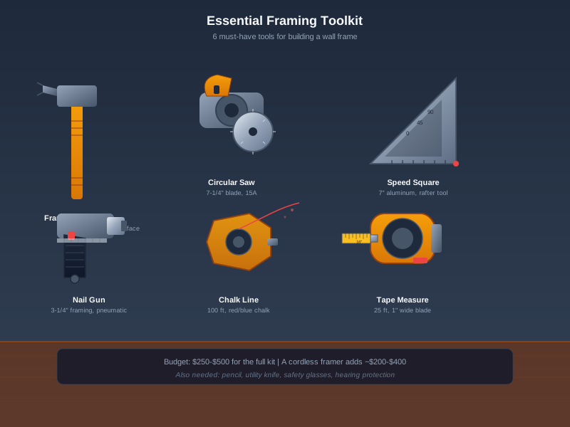
Framing Tool Kit — Five Essentials
The right tools make the difference between a wall that goes up square in two hours and one that fights you all afternoon. You can frame an entire house with these five tools plus a chop saw and a pneumatic nailer; skip any one and you will be compensating with tape, shims, and swearing. Each tip below comes from a crew lead who framed 300+ homes with the exact same kit.
Framing Square (Steel Square)
L-shaped metal tool with a 24″ blade and a 16″ tongue meeting at 90°. Used for laying out O.C. marks, cutting rafter angles, and verifying square corners.
Use the body edge to lay out every 16″ or 24″ stud mark in a single long run — it is faster and straighter than a tape alone.
Speed Square (Rafter Angle Square)
Triangular 7-inch aluminum square that lives in a toolbelt pouch. Combines a try square, mitre square, protractor, and line scriber in one.
Swivel the edge to the pitch mark for quick rafter cuts, or use the flange to hook a 2× and draw a perfect 90° cut line every time.
Chalk Line (Snap Line)
Marks long straight lines on floors, plates, and sheathing by snapping a taut, chalk-dusted cord.
For plate layouts over 20 ft, strike two reference lines — the sole-plate line AND a parallel offset at 3 ft — so you can quickly re-square the wall after standing it.
6-Ft Level & Laser Plumb
Checks studs and walls for plumb; a laser level projects a 360° horizontal line for aligning top plates across many studs at once.
A 6-ft level catches crowns and bows that a 4-ft level misses — use it on every third stud and always on king studs flanking openings.
Pneumatic Framing Nailer
Drives 16d and 10d nails into lumber in 0.1 seconds per shot, dramatically increasing production.
Watch the depth-of-drive: if nails blow through 3-2 or bury too deep, dial the regulator down. Under-driven heads pop drywall later.
IRC Code Compliance Notes
Referenced from the 2021 International Residential Code — confirm your local jurisdiction's adopted edition before building.
General Rule — IRC 2021 R602.3.1
Stud size and spacing for wood walls are set by IRC Section R602.3.1: 16 inches on-center is the general case, and 24-inch spacing is allowed for many walls depending on stud size, wall height, and the load above, with one- and two-story limits shown in Table R602.3.1(1) and (2). Always confirm the table for your exact wall height before ordering.
Load-Bearing vs Non-Load-Bearing
Non-load-bearing interior partitions may be framed 24″ O.C. with 2×4 studs at any reasonable height. Load-bearing and taller walls have stricter limits. If you are adding or moving a wall and are not sure whether it is bearing, look for joists running perpendicular on the floor above — if they land on the plate, the wall is almost certainly bearing and needs a header or beam before any stud gets removed.
Header Spans — IRC R602.7
Header size depends on the clear span and the tributary load above (roof, floor, or both). A 3′-0″ opening under a light roof load typically needs a double 2×10 or double 2×12 built-up; verify the span table in the code or the engineered plans, and always use a jack stud under each end. Wide openings over 6 feet often require doubled jack studs and an LVL engineered header instead of built-up 2× stock.
Bottom Plate on Concrete
IRC R602.1.2 requires the bottom (sole) plate in direct contact with concrete or masonry to be naturally decay-resistant wood or pressure-treated (PT) material rated for ground contact. Seams and intersections are treated equally. PT stamps must be visible to the inspector — a material certificate in the file is not enough; the stamp must be on the board itself.
Fire Blocking — IRC R302.11
Stud cavities over 8 ft tall need fire blocking at floor/ceiling lines and at horizontal shifts. Nominal 2× blocking, mineral wool batt, or ½″ plywood strips are common means — confirm your local building department's accepted details before installing, because some jurisdictions require fire caulking at every penetration through the fire-stop plane.
Skill Roadmaps: Beginner → Intermediate → Advanced
Framing mastery builds from recognizing parts to laying out plates to optimizing a whole-house bid. Each roadmap below maps the guides on this site to your current skill level. Follow the beginner path end-to-end and you will be comfortable standing a partition solo; follow the advanced path and you will be the estimator who beats the competition on price without cutting corners.
Beginner — Framing Foundations
Understand the parts and how they fit together
- 1Read Wall Framing Diagram guide — Components legend + SVG library
- 2Learn 16″ O.C. layout marks on plates with a framing square
- 3Memorize nominal vs actual: 2×4 = 1½″×3½″, precut 92⅝″ for 8 ft wall
- 4Run main calculator on a 12-ft interior partition and verify count by hand
Intermediate — Takeoff & Budgeting
Turn plans into orders and bids
- 1Split plans into exterior vs interior and run each wall through main calculator
- 2Open 2×4 Calculator for bundle count, precut heights, and board-foot pricing
- 3Run Framing Cost Calculator for whole-house budget with regional labor rates
- 4Add 15% waste and round up to bundles; export PDF cut list
Advanced — Production & Code Mastery
Optimize layouts, nail connections, and inspector hand-off
- 1Compare 16″ vs 19.2″ vs 24″ O.C. scenarios on every wall run
- 2Implement 2-stud OVE corners + ladder T-intersections for max insulation
- 3Verify header spans against IRC R602.7; upgrade to LVL for 6-ft+ openings
- 4Compare steel vs wood on TI/basement scope via Metal Stud guide matrix
🔍 Pre-Inspection Walkthrough Checklist
The cost of fixing a framing mistake after drywall goes up is 10× the cost of catching it before sheathing. Every guide on this site emphasizes the same pre-sheathing walk-through: count every stud against your cut list, pull a diagonal to confirm square, confirm every PT plate stamp is visible, spot-check nail counts per plate connection, and verify every header end sits on a jack stud with a 16d toenail. Spend 10 minutes now and you will never be the contractor pulling 12 sheets of drywall off because an inspector caught a missing jack stud.
The Framing Diagram guide includes a printable 22-point inspection checklist you can laminate and carry in your tool pouch, with per-component pass/fail boxes and a signature line for your on-site QC lead.
🧱 Framing Against Concrete: Basement Wall Framing Basics
Basement framing follows the same stud layout math as every other wall on this site — the difference is what sits under the sole plate. Concrete never dries out completely, so code and durability both push you toward a pressure-treated (PT) bottom plate, a capillary break between wood and slab, and a small assembly tolerance rather than a dead-tight fit. Nail the wood-to-concrete joint with 3″ concrete nails, Titen screws, or a powder-actuated fastener at 16″ O.C., keeping fasteners at least ¾″ from board edges so PT stock does not split.
- PT sole plate + gap strategy — run the bottom plate on a foam sill-seal strip or leave a 1/2″ inch of clearance to the wall face; never set untreated lumber directly on slab.
- Furring vs stud walls — glued 1× furring or rigid-foam-only walls suit mild basements, but any finished space with outlets and insulation deserves true 2×4 partitions at 16″ O.C., framed 1/2″ off the masonry to create a thermal break.
- Soffits & duct bulkheads — box mechanicals with short cripple walls hung off the top plate instead of full-height studs; they are the most commonly missed line in basement material orders.
When budgeting a basement finish, pair this page with the Framing Cost Calculator guide’s per-linear-foot basement rates ($4.50–$8.00 per lin ft for 2×4 walls depending on insulation). Then generate the exact stud, plate, and concrete-anchor counts by entering each basement wall into the homepage calculator — treat it as your basement wall framing calculator and add one extra anchor point per door opening in the takeoff.
Size Your Basement Walls in the Calculator →Framing Guides FAQ
What do these framing guides cover that the main calculator does not?▼
The main homepage calculator is a math engine that takes wall length and spacing and returns a stud count. These framing guides go deep into the context and methodology around that math. The Wall Framing Diagram guide annotates six wall types with SVG callouts and compares three layout methods side by side. The Framing Cost guide rolls studs, plates, labor, and overhead into a per-square-foot benchmark with 2026 regional rates. The Metal Stud guide compares gauge-by-gauge pricing to wood. The 2×4 guide adds bundle economics and precut procurement recommendations. Every guide includes its own embedded formulas, worked examples, and either a calculator or a sizing matrix.
Which framing guide should I read first?▼
If you are bidding a whole-house project, start with the Framing Cost Calculator guide to get a per-square-foot benchmark range. If you are laying out walls on a set of plans, start with the Wall Framing Diagram guide for the annotated SVG library and the 16″ vs 19.2″ vs 24″ layout comparison. If you need to order lumber today, start with the 2×4 Stud Calculator guide for the bundle economics and precut height tables. If the scope is commercial or basement TI, start with the Metal Stud Framing Cost guide for the gauge-by-gauge pricing and steel-vs-wood direct comparison.
How do I read a wall framing diagram?▼
Every annotated wall framing diagram uses the same legend: hollow rectangles are field studs, solid rectangles are king studs, hatched rectangles are jack/trimmer studs, short rectangles above a header are header cripples, and short rectangles below a window sill are sill cripples. Dotted lines show plate edges. Dimensions in green are on-center spacing; dimensions in black are full lengths. The Wall Framing Diagram guide on this site walks through each legend item with a cross-section cutaway so you never confuse a jack stud with a king stud on a 90° corner build-up.
What is the difference between 16″ O.C., 19.2″ O.C., and 24″ O.C. layout?▼
16″ O.C. is the default load-bearing spacing — three bays per 4-ft sheet, every sheet break lands on a stud. 24″ O.C. uses about 33% fewer studs and is allowed for non-bearing partitions and 2×6 OVE exterior walls. 19.2″ O.C. is the production-builder middle ground that puts exactly 5 studs over two 4-ft sheets, saving 20% lumber vs 16″ O.C. while still landing a stud at every 4-ft sheet joint. The Layout Methods section on the diagram guide compares all three modes with stud-per-foot counts, panel-alignment notes, and IRC code references.
How many extra studs does a door or window add?▼
A standard 3-foot interior door adds roughly 4–5 studs beyond the field count: two full-height king studs (one each side), two shorter jack/trimmer studs under the header ends, plus header framing. A 3-foot window adds 5–6 studs because you also need a rough sill at the bottom and 2–4 sill cripples supporting it from below. Wide patio sliders and large picture windows add 7–9 studs because they use doubled or tripled trimmers under larger headers. The Opening Extras section in the Wall Framing Diagram guide walks through each of these with per-opening stud-count tables.
Should I frame with 2×4 or 2×6 exterior walls?▼
Choose 2×6 whenever any of these is true: the exterior wall is in climate zone 5 or colder (needs R-19+ cavity insulation), plumbing pipes run inside the exterior wall, the wall height exceeds 10 ft, or you plan to use 24″ O.C. advanced framing. A 2×6 wall costs 30–40% more in lumber but the deeper R-value pays back the premium in 5–10 years of lower heating/cooling bills in cold climates. For interior partitions and warm-climate exteriors with no plumbing, 2×4 at 16″ O.C. remains the baseline. The 2×4 vs 2×6 comparison table in the Cost Guide gives side-by-side numbers.
What nails and how many per framing connection?▼
Studs face-nailed to the plate use two 3½″ 16d common nails per end; toenail connections use three 3″ 10d sinkers angled through the stud. Double top plates get 16d commons every 16″ along the lap. Sheathing uses 8d ring-shank nails at 6 inches on edges and 12 inches in the field per code. If using a pneumatic nailer, match the nail specification (collation angle, shank diameter, and head style) to the gun. The Nails & Tool Guide section of the Framing Diagram guide includes a full per-connection nail table with nail sizes, pennyweights, and counts.
Do I need a permit to frame a wall in my house?▼
Non-load-bearing interior partitions usually do not require a permit in most US jurisdictions. Adding or moving load-bearing walls, framing an addition or accessory structure, or any change that redistributes a roof or floor load almost always requires a permit, plan review, and inspections. Framing an addition with exterior walls requires one even if the floor area is tiny — it triggers zoning setback, egress, and structural reviews. When in doubt, call your local building department — a 5-minute phone call beats ripping out un-permitted work during a future sale inspection.
How much waste factor should I add to my framing lumber takeoff?▼
Add 10% for a simple straight interior partition with zero or one opening. Use 15% as the default industry baseline — it covers culled boards, crowned studs, the occasional mis-cut, cut-offs around openings, and blocking pieces. Use 20% for walls with multiple windows and doors, layouts with jogs or bay breaks, or gable-end rake walls where every stud gets a custom angle cut. Use 25% for curved walls, arches, custom plans, or self-perform first-time framing crews. Never order the exact takeoff count without waste; even the best framers eat a stud or two per lift.
What is the standard sequence for building a wall frame?▼
The industry-standard 11-step sequence is: (1) measure and snap the plate line, (2) gather material and cut the three plates, (3) lay out O.C. marks on the plates, (4) mark rough openings, (5) cut studs, kings, jacks, cripples, and headers, (6) assemble the wall flat on the deck, (7) square, temporarily brace, and stand it, (8) anchor the sole plate to the floor, (9) plumb, permanent brace, and nail the second top plate, (10) install blocking, fire stops, and let-in bracing, (11) build corners and intersections and hand off to the next trade. The How to Build a Wall Frame section of the Diagram guide walks each step with gotchas and common rookie mistakes.
Putting the Framing Guides Together
The guides on this page share one model: a wall is eight defined components (studs, plates, headers, sills, cripples, kings, jacks, corners), spaced at one of three standard O.C. modes, built in a fixed 11-step sequence, nailed per IRC schedule, inspected before sheathing, and costed using a consistent material-plus-labor benchmark. Every calculator on this site — the main homepage engine plus the dedicated cost, 2×4, and metal-stud tools — returns numbers that plug directly into that shared model. If the Wall Framing Diagram guide says an opening adds 5 studs, the 2×4 Calculator does the same. If the Framing Cost guide says labor is 50–60% of installed scope, the cost calculator uses that same percentage band.
The real skill is not reading any one guide in isolation — it is connecting them. A beginner reads the diagram guide once, memorizes the components, and stands a straight partition. An intermediate estimator reads the diagram guide, the 2×4 procurement guide, and the cost guide back to back, then runs two layout scenarios (16″ vs 24″ O.C.) to see whether a 300-stud reduction pays back the 2×6 upgrade on a 2,000 ft² spec home. An advanced production builder reads every guide plus the IRC code notes, designs the plan with 2-stud OVE corners and ladder-block T-intersections, and delivers a bid that is 8% lower than the competition while still passing energy code on the first inspection.
You do not need to read every guide on this page today. Start with the roadmap matched to your level, open the one guide that answers your immediate question, and run the companion calculator alongside it. Bookmark this page and keep it open on your next framing project — when you are kneeling on the deck with a chalk line in one hand and a plan in the other, these are the references you will reach for to make sure every mark, every nail, and every dollar is right the first time.